Final truss design assembled and hung up to simulate viewing it as a truss from underneath
       
     
 Detail of the bolting pattern showing the joint where 4 different  unique pieces come together.
       
     
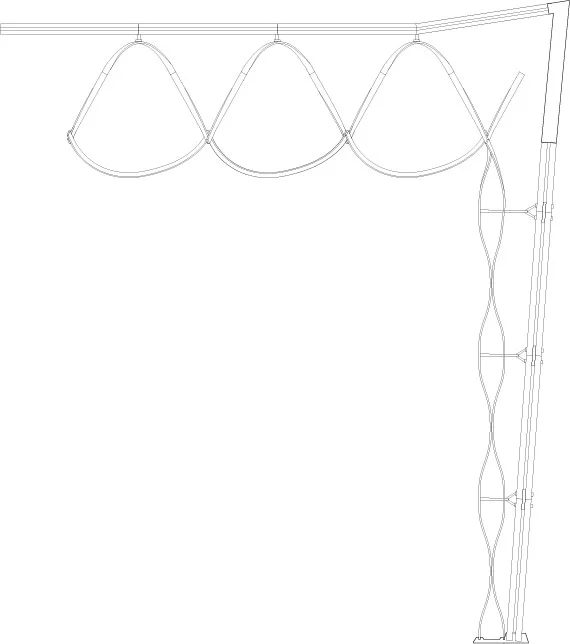
 Enclosure wall detail showing how the truss would look attached to an enclosure and ceiling system.
       
     
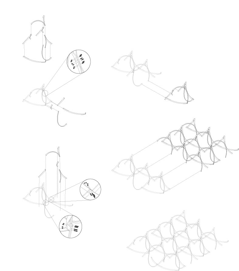
 Exploded assembly drawing showing how the truss modules come together and also how different modules connect to each other to array in all directions.
       
     
 Drying jig setup for the top half of the truss module pieces. This setup allows the steambent wood to dry in the right shape to be assembled into the final truss.
       
     
 Separate drying jig for the truss crossbraces.
       
     
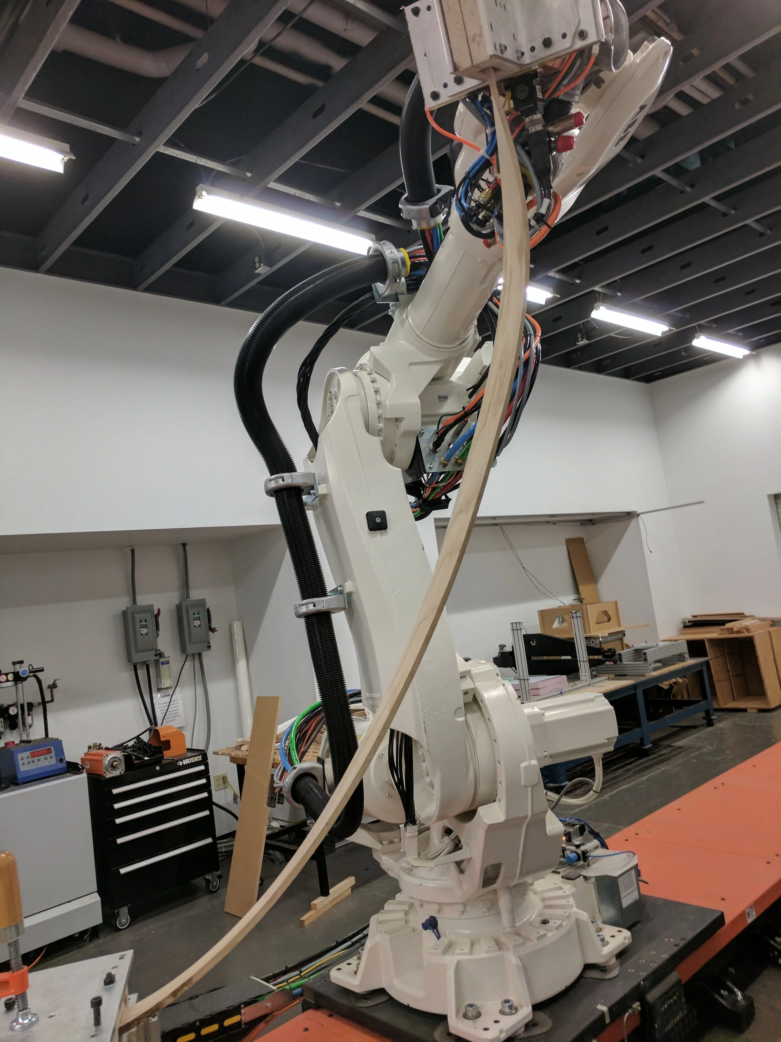
 Robot bending our longest piece, one of our truss crossbracing pieces which is about 6' long.
       
     
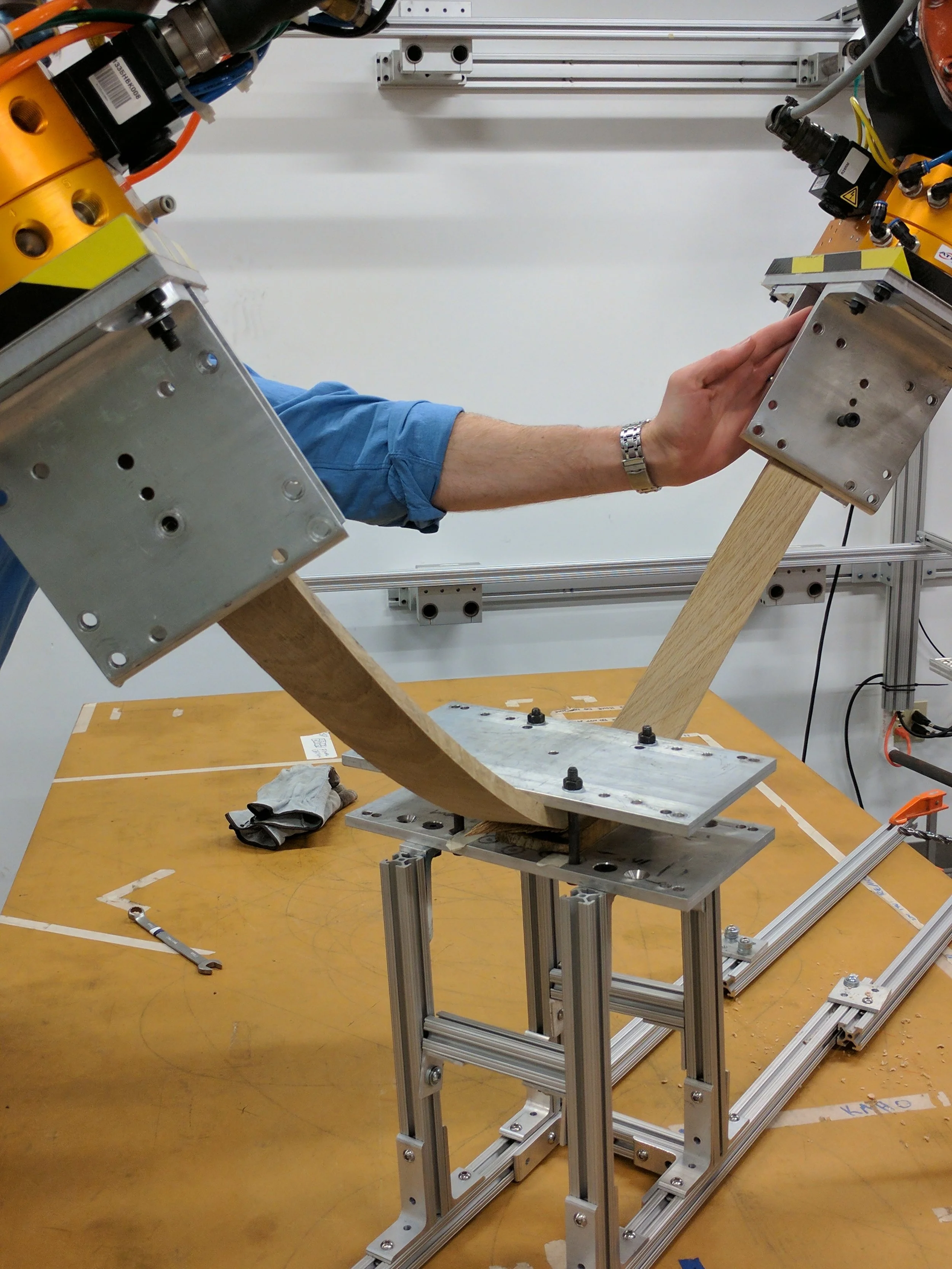
 Top arch piece being bent by the robots using a fixture as a fixed center control point and the ends of the robots as the remaining 2 control points.
       
     
 Fixture setup and wood loading for short end pieces.
       
     
 First test bend with the robots using foam to check the bending angles and robot speeds.


Timber Studio Documentation

Documentation for Timber Studio Spring 2017 at CMU under Joshua Bard
Collaboration between me, Ai Fukuda, Trent Wimbiscus, and Jack Fogel.

This assortment of pictures and videos show how we tested different bending fixtures and setups and how we developed different bends and robot toolpaths in order to create the different unique parts we needed for the final truss assembly.

 Final truss design assembled and hung up to simulate viewing it as a truss from underneath


Final truss design assembled and hung up to simulate viewing it as a truss from underneath

 Detail of the bolting pattern showing the joint where 4 different  unique pieces come together.


Detail of the bolting pattern showing the joint where 4 different  unique pieces come together.

 Enclosure wall detail showing how the truss would look attached to an enclosure and ceiling system.


Enclosure wall detail showing how the truss would look attached to an enclosure and ceiling system.

 Exploded assembly drawing showing how the truss modules come together and also how different modules connect to each other to array in all directions.


Exploded assembly drawing showing how the truss modules come together and also how different modules connect to each other to array in all directions.

 Drying jig setup for the top half of the truss module pieces. This setup allows the steambent wood to dry in the right shape to be assembled into the final truss.


Drying jig setup for the top half of the truss module pieces. This setup allows the steambent wood to dry in the right shape to be assembled into the final truss.

 Separate drying jig for the truss crossbraces.


Separate drying jig for the truss crossbraces.

 Robot bending our longest piece, one of our truss crossbracing pieces which is about 6' long.


Robot bending our longest piece, one of our truss crossbracing pieces which is about 6' long.

 Top arch piece being bent by the robots using a fixture as a fixed center control point and the ends of the robots as the remaining 2 control points.


Top arch piece being bent by the robots using a fixture as a fixed center control point and the ends of the robots as the remaining 2 control points.

 Fixture setup and wood loading for short end pieces.


Fixture setup and wood loading for short end pieces.

 First test bend with the robots using foam to check the bending angles and robot speeds.


First test bend with the robots using foam to check the bending angles and robot speeds.